Equalization#
EQ is an integral part of music production and widely used in the production and consumption of music, where a filter bank is used as a corrective filter to reduce masking [ValimakiR16], i.e. overlapping of sound sources, or as a creative tool to shape sonic characteristics [SRDM19]. It consists of the modification of frequency content through positive or negative gains which change the harmonic and timbral characteristics of the audio.
This is done for a variety of reasons, such as a corrective or technical filter to lessen masking within mixes, to change a speaker system’s frequency response, or as an artistic or creative tool while recording a particular audio source [MartinezRamirez20].
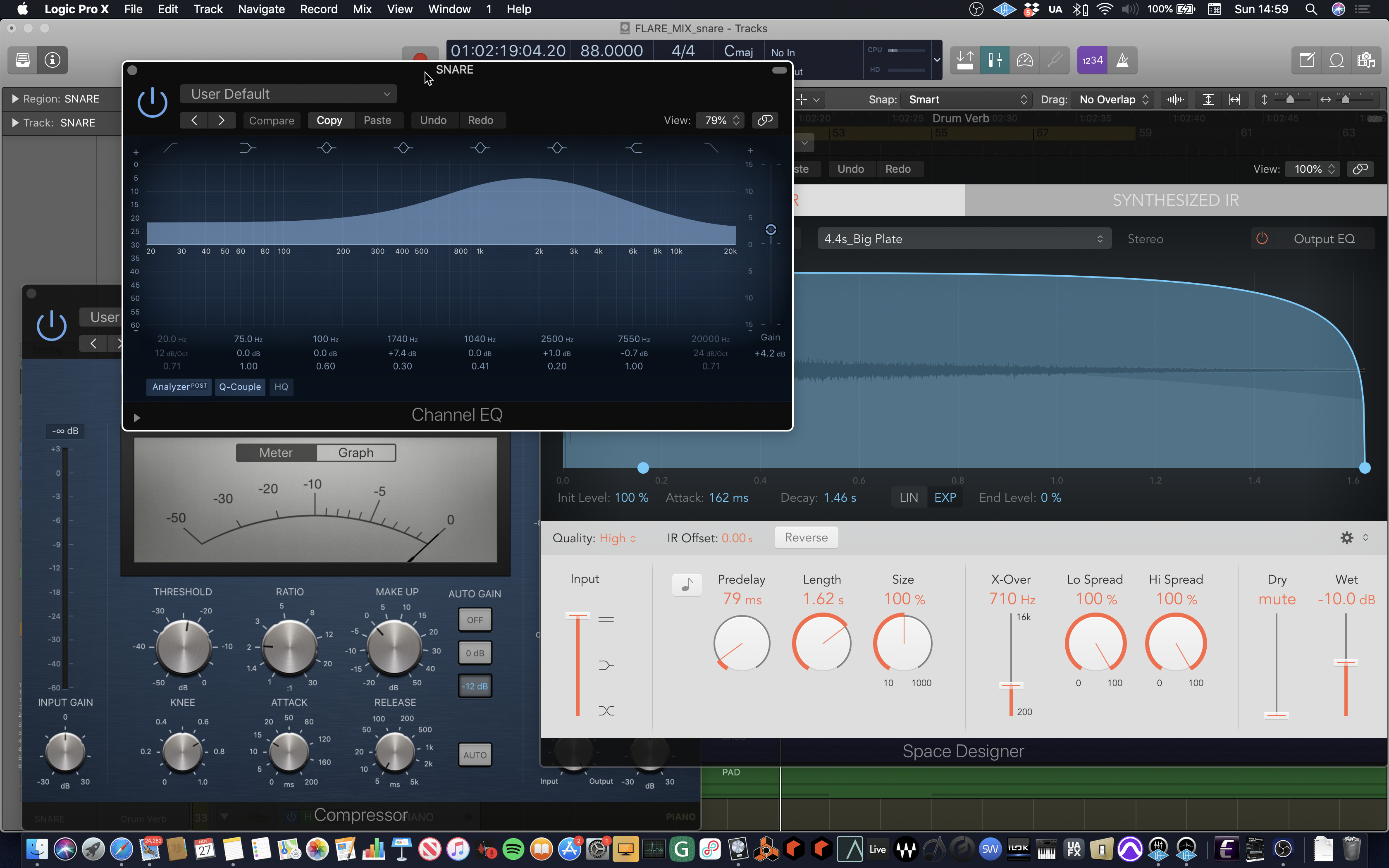
Thus, EQ is the process of altering or adjusting the amplitude of various frequencies of a sound. It can be used to enhance or sculpt a sound adding character or removing imperfections. In our video we show how equalisation of the vocal sound is used to add clarity and presence in the higher frequencies, around 3 kHz, along with warmth in the lower frequencies around 250 Hz (see Fig. \ref{snareeq}). The use of semantic descriptors to articulate technical changes is key to the process.

Fig. 5 Processing of the snare drum in Logic Pro.#
equalizer is normally implemented via a filter bank whose coefficients are obtained from the designed cut-off frequency \(f_{c}\) and quality factor \(Q\). EQ can be implemented in both the time-domain and the frequency-domain and is often performed through a gain \(G\) at a given \(f_{c}\) and \(Q\) [VZolzerA06].
The filter bank consists of Finite Impulse Response (FIR) or Infinite Impulse Response (IIR) filters, whose main difference corresponds to the absence or presence of feedback loops [Gay04]. The non-recursive FIR discrete difference equation is
where \(y(n)\) is the output signal, \(x(n)\) is the input signal and \(a_{k}\) corresponds to the \(M\) filter coefficients. This non-recursive system is characterized by being a weighted sum of delayed inputs, thus a general FIR filter consists of a feed-forward system with \(M-\)1 delay lines. The recursive IIR discrete difference equation is
The IIR systems are characterized by a weighted sum of delayed inputs and outputs. This feedback system consists of an input delay line of \(M-\)1 elements and an output delay line of \(N\) elements. The recursive coefficients are \(b_{k}\).% [MartinezRamirez20].
The various types of filters can be classified into the following classes [Zolzer11]. These types of filters can be implemented via FIR or IIR filters whose coefficients determine \(G\), \(f_{c}\) and \(Q\). Most of the widely used EQs are based on the following filter types.
Lowpass#
Attenuates frequencies above \(f_{c}\) and \(Q\) determines a boost or resonance of frequencies around \(f_{c}\).
Fig. 6 Lowpass filter resopnse.#
Highpass#
Attenuates frequencies below \(f_{c}\) and \(Q\) determines a boost or resonance of frequencies around \(f_{c}\).
Fig. 7 Highpass filter resopnse.#
Bandpass#
Attenuates frequencies above and below a frequency band with bandwidth \(f_{b}\) and center frequency \(f_{c}\). \(Q\) is the relative bandwidth \(f_{c}\)/ \(f_{b}\). A bandreject filter attenuates frequencies within the frequency band.
Fig. 8 Bandpass filter resopnse.#
Shelving#
A low-frequency shelving filter (lowshelf) boosts or cuts frequencies below \(f_{c}\) while preserving frequencies above \(f_{c}\). A high-frequency shelving filter (highshelf) boosts or cuts frequencies above \(f_{c}\) while preserving frequencies below \(f_{c}\). \(Q\) determines the resonance of frequencies around \(f_{c}\).
Fig. 9 Shelving filter resopnse.#
Peaking#
This filter boosts frequencies between a bandwidth \(f_{b}\) with center frequency \(f_{c}\) while preserving frequencies outside this frequency band. A notch filter cuts frequencies within the frequency band.
Fig. 10 Peaking filter resopnse.#
